ADRF5730 Datasheet
0.5 dB LSB, 6-Bit, Silicon Digital Attenuator, 100 MHz to 40 GHz
0.5 dB LSB, 6-Bit, Silicon Digital Attenuator, 100 MHz to 40 GHz
| Part No. | In Stock | Price | Packaging | SPQ | Marking | MSL | Pins | Temp Range | Package Description |
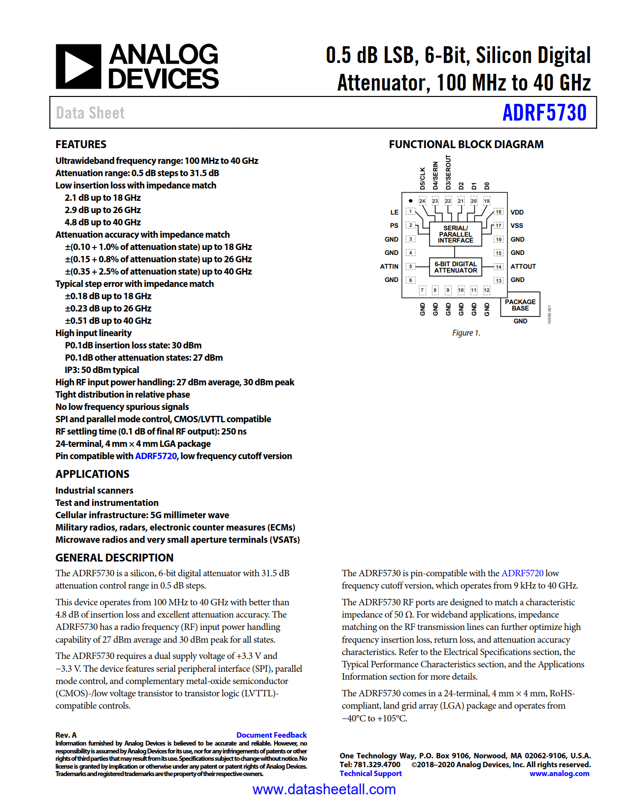
The ADRF5730 is a silicon, 6-bit digital attenuator with 31.5 dB attenuation control range in 0.5 dB steps.
This device operates from 100 MHz to 40 GHz with better than 4.8 dB of insertion loss and excellent attenuation accuracy. The ADRF5730 has a radio frequency (RF) input power handling capability of 27 dBm average and 30 dBm peak for all states.
The ADRF5730 requires a dual supply voltage of +3.3 V and −3.3 V. The device features serial peripheral interface (SPI), parallel mode control, and complementary metal-oxide semiconductor (CMOS)-/low voltage transistor to transistor logic (LVTTL)-compatible controls.
The ADRF5730 is pin-compatible with the ADRF5720 low frequency cutoff version, which operates from 9 kHz to 40 GHz.
The ADRF5730 RF ports are designed to match a characteristic impedance of 50 Ω. For wideband applications, impedance matching on the RF transmission lines can further optimize high frequency insertion loss, return loss, and attenuation accuracy characteristics. Refer to the Electrical Specifications section, the Typical Performance Characteristics section, and the Applications Information section for more details.
The ADRF5730 comes in a 24-terminal, 4 mm × 4 mm, RoHS-compliant, land grid array (LGA) package and operates from −40°C to +105°C.