MAX199 Datasheet
8-Channel, Multi-Range, 5V, 12-Bit DAS with 8+4 Bus Interface and Fault Protection
8-Channel, Multi-Range, 5V, 12-Bit DAS with 8+4 Bus Interface and Fault Protection
| Part No. | In Stock | Price | Packaging | SPQ | Marking | MSL | Pins | Temp Range | Package Description |
The MAX199 multi-range, 12-bit data-acquisition system (DAS) requires only a single +5V supply for operation, and converts analog signals up to ±4V at its inputs. This system provides eight analog input channels that are independently software programmable for a variety of ranges: ±VREF, ±VREF/2, 0V to VREF, or 0V to VREF/2. This increases effective dynamic range to 14 bits, and provides the user flexibility to interface 4mA-to-20mA, ±12V, and ±15V powered sensors to a single +5V system. In addition, the converter is fault-protected to ±16.5V; a fault condition on any channel will not affect the conversion result of the selected channel. Other features include a 5MHz bandwidth track/hold, 100ksps throughput rate, internal/external clock, internal/external acquisition control, 8+4 parallel interface, and operation with an internal 4.096V or external reference.
A hardware active-low SHDN pin and two programmable power-down modes (STBYPD, FULLPD) provide low-current shutdown between conversions. In STBYPD mode, the reference buffer remains active, eliminating start-up delays.
The MAX199 employs a standard microprocessor (µP) interface. Its three-state data I/O interface is configured to operate with 8-bit data buses, and data-access and bus-release timing specifications are compatible with most popular µPs. All logic inputs and outputs are TTL/CMOS compatible.
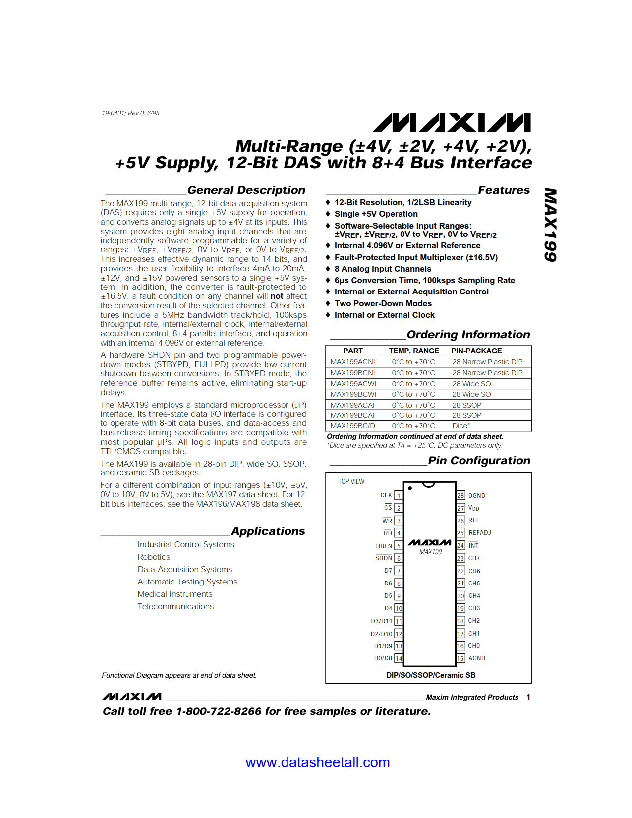
The MAX199 is available in 28-pin DIP, wide SO, SSOP, and ceramic SB packages.
For a different combination of input ranges (±10V, ±5V, 0V to 10V, 0V to 5V), see the MAX197 data sheet. For 12-bit bus interfaces, see the MAX196/MAX198 data sheet.