LTC1041 Datasheet
BANG-BANG Controller
BANG-BANG Controller
| Part No. | In Stock | Price | Packaging | SPQ | Marking | MSL | Pins | Temp Range | Package Description |
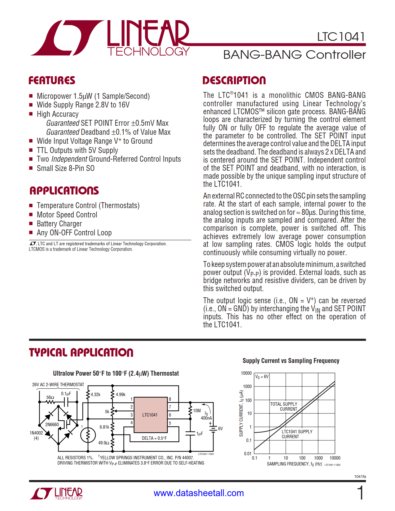
The LTC1041 is a monolithic CMOS BANG-BANG controller manufactured using Linear Technology’s enhanced LTCMOS™ silicon gate process. BANG-BANG loops are characterized by turning the control element fully ON or fully OFF to regulate the average value of the parameter to be controlled. The SET POINT input determines the average control value and the DELTA input sets the deadband. The deadband is always 2 × DELTA and is centered around the SET POINT. Independent control of the SET POINT and deadband, with no interaction, is made possible by the unique sampling input structure of the LTC1041.
An external RC connected to the OSC pin sets the sampling rate. At the start of each sample, internal power to the analog section is switched on for ≈ 80µs. During this time, the analog inputs are sampled and compared. After the comparison is complete, power is switched off. This achieves extremely low average power consumption at low sampling rates. CMOS logic holds the output continuously while consuming virtually no power.
To keep system power at an absolute minimum, a switched power output (VP-P) is provided. External loads, such as bridge networks and resistive dividers, can be driven by this switched output.
The output logic sense (i.e., ON = V+) can be reversed (i.e., ON = GND) by interchanging the VIN and SET POINT inputs. This has no other effect on the operation of the LTC1041.